
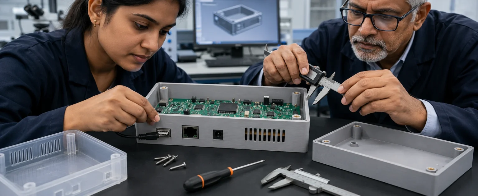
The enclosure CAD appears aligned, but actual PCB tolerances, connectors, cables and screws create cumulative variation. A physical fit-check is needed before production tooling. This article explains how 3D printed enclosure Noida should be evaluated from the customer-problem, engineering-decision and commercial-buyer perspectives. It also shows what information should be shared with a professional manufacturing partner so the quotation, process and final part are aligned with the real project objective.
A CAD assembly can identify obvious interference, but real PCBs, connectors, cables and fasteners reveal handling and tolerance issues. Use production-intent components where possible during the prototype review. Functional nylon components, fixtures and complex geometries may be suitable for SLS 3D printing.
Quick Answer
3D printed enclosure Noida is most useful when it is selected around a real engineering and commercial objective. Validate the enclosure physically — PCB support and clearance, ports and connectors, screw bosses, snap-fits and clips, and ventilation and heat zones — using production-intent components, then record dimensional and assembly feedback with controlled revision notes before moving to tooling.
Why Enclosure Validation Matters
- The enclosure CAD appears aligned, but actual PCB tolerances, connectors, cables and screws create cumulative variation that only a physical fit-check reveals.
- Real components uncover handling and tolerance issues that a CAD assembly cannot show.
- Fit-checking before production tooling identifies assembly risks early, avoiding expensive tooling corrections.
- A connector may fit the opening but still be difficult for the user to access — only a physical check proves it.
- Documented findings turn every prototype into a controlled step toward the next revision.
Where Excel Rapidtech Fits
Excel Rapidtech can manufacture and review 3D-printed enclosure prototypes for Noida product teams, helping them identify assembly risks before injection-moulding tooling. Excel Rapidtech can review the CAD model, application, quantity, material expectation, finish and critical dimensions before recommending a suitable route. The company's wider service structure allows projects to be considered across 3D printing, SLA, SLS, vacuum casting, CNC machining, design support and post-processing rather than being forced into one method.
Comparison
| Decision area | Option or condition A | Option or condition B |
|---|---|---|
| PCB fit | Support, clearance and insertion path | |
| Ports | Connector centreline and access | |
| Bosses | Pilot hole, wall thickness and torque | |
| Clips | Engagement and repeated opening | |
| Assembly | Fastener sequence and service access |
Step-by-Step Workflow
- Check PCB support and clearance: confirm the board rests on the intended posts, avoids contact with the enclosure and has space for solder joints and tall components. Review the board insertion path as well as the final position.
- Check ports and connectors: insert the actual plugs, cables and accessories. Confirm alignment, grip clearance and strain relief. A connector may fit the opening but still be difficult for the user to access.
- Check screw bosses: evaluate boss diameter, wall thickness, pilot hole and distance from edges. Tightening can split weak bosses or distort the enclosure. Select the fastening method according to how often the product will be opened.
- Check snap-fits and clips: test insertion force, engagement and removal. A brittle prototype material may not represent the final production plastic, so interpret failures carefully and review geometry as well as material.
- Check ventilation and heat zones: confirm that vents are not blocked by internal components and that hot areas have adequate physical clearance. Use thermal testing separately when actual heat performance is important.
- Record dimensional and assembly feedback: measure critical interfaces and photograph assembly problems. Update the CAD with a controlled revision note so that the next prototype addresses specific findings.
Common Mistakes to Avoid
- Testing without the real PCB and plugs.
- Ignoring solder and component height.
- Using a single screw test for repeated opening.
- Not measuring port offsets.
- Changing CAD without documenting test results.
What to Measure
- Board support and standoff height, defined in measurable terms.
- Connector opening alignment, defined in measurable terms.
- Screw boss strength, defined in measurable terms.
- Snap-fit insertion force, defined in measurable terms.
- Assembly sequence and access, defined in measurable terms.
- What to include in a quotation request: preferred file format, quantity, application, target material behaviour, critical dimensions, tolerance where genuinely required, surface finish, colour and delivery requirement, plus drawings and mating components where possible.
How to Choose a Professional 3D Printing Process
The best process depends on what the prototype must prove. SLA is commonly selected when fine details and a smooth surface are important. SLS is often preferred for complex nylon parts, clips and functional assemblies. Vacuum casting may follow a finished master when several similar polymer parts are required. CNC machining may be more appropriate where the design, material or tolerance is better served by subtractive manufacturing. A professional provider should explain the trade-off instead of recommending the same technology for every file.
Factors That Affect Cost and Delivery
Price and lead time are shaped by part size, build volume, orientation, material, quantity, support removal, surface finishing, painting, assembly and inspection. File problems and unclear requirements can cause more delay than the print itself. Buyers should provide a complete technical brief and respond quickly to manufacturability questions. For local projects, proximity can simplify communication and collection, but it does not replace technical planning or quality control.
A Step-by-Step Decision Framework
- Define the business decision the part must support. Examples include design approval, fitment validation, customer trial, tooling release or a limited pilot batch.
- Identify the technical risks. Mark interfaces, critical dimensions, loads, environmental exposure, visible surfaces and features that may fail during assembly.
- Select the process around those risks. Compare geometry, material behaviour, quantity, finish and design stability rather than choosing only by familiarity or lowest price.
- Agree on acceptance criteria. State what will be measured, assembled, tested or visually approved before the part is accepted.
- Control revisions and approvals. Use a clear file number, record feedback and freeze the approved version before the next manufacturing stage.
How to Compare Local 3D Printing Suppliers
Compare process range, engineering review, material information, finishing, inspection, confidentiality, revision control and communication. Ask whether the supplier can explain why a process is suitable for the application. Review what is included in the quotation and whether critical dimensions will be checked. A professional service should help reduce project risk, not merely convert file volume into a price.
Conclusion
The right use of 3D printed enclosure Noida begins with a clearly defined problem and ends with an evidence-based manufacturing decision. Buyers should connect design maturity, geometry, material behaviour, quantity, finish, inspection and commercial risk instead of selecting a process only by unit price. A detailed brief makes quotations more comparable and helps the manufactured part answer the question it was created to test. Share your CAD file, required quantity, application, critical dimensions and finish expectations with Excel Rapidtech for a technical feasibility review.
Ready to discuss your part?
FAQs
Why validate an enclosure with real components instead of CAD only?
A CAD assembly can identify obvious interference, but real PCBs, connectors, cables and fasteners reveal handling and tolerance issues. Use production-intent components where possible during the prototype review.
What should be checked for PCB support and clearance?
Confirm the board rests on the intended posts, avoids contact with the enclosure and has space for solder joints and tall components. Review the board insertion path as well as the final position.
What should be checked on ports and connectors?
Insert the actual plugs, cables and accessories. Confirm alignment, grip clearance and strain relief. A connector may fit the opening but still be difficult for the user to access.
What should be checked on screw bosses?
Evaluate boss diameter, wall thickness, pilot hole and distance from edges. Tightening can split weak bosses or distort the enclosure. Select the fastening method according to how often the product will be opened.
How should snap-fit failures in a prototype be interpreted?
Test insertion force, engagement and removal. A brittle prototype material may not represent the final production plastic, so interpret failures carefully and review geometry as well as material.
How should dimensional and assembly feedback be recorded?
Measure critical interfaces and photograph assembly problems. Update the CAD with a controlled revision note so that the next prototype addresses specific findings.
Related Reading
- How Noida Electronics Companies Can Prototype Enclosures Before Injection Moulding
- How Delhi Automotive and Electronics Companies Use 3D Printing for Product Validation
- How Gurgaon Product Companies Can Choose Between SLA and SLS Prototyping
- 3D Printing for Noida Manufacturers: Prototypes, Jigs, Fixtures and Replacement Parts
- How Noida Startups Can Develop a Working Hardware Prototype Before Fundraising or Production